Georg Ohm's Law
As with ham radio in general, this column has readers at all levels of technical expertise. Ohm's law might seem basic to many, but to others it's seldom used and in the category of “once learned then forgotten.” As a practicing EE, Ohm's law is second nature to me. It's one of the lenses through which I view the everyday world. I can't see a transceiver, or a power supply, or an antenna, or power lines, or a toaster without thinking about how many amps, volts and/or watts are involved.
Meanwhile, most of us are not EEs. The good news is we don't have to be to enjoy ham radio. Far from it! In this column, in my book and in my presentations I've shared my belief that very little math is required to enjoy ham radio. You don't need an engineering degree to be a happy, successful ham. Actually, you don't need any math skills at all. But, a little knowledge is a good thing. Were I asked to name one technical concept I suggest every ham know and know well, I'd answer Ohm's law: E =I*R. The various permutations of Ohm's Law can all be handled with a four-function calculator.
So, let's take a look at Ohm's law, beginning with a brief history.
Before Georg Ohm began laying the foundation for the monthly electric bill there was Henry Cavendish (1731-1810). A shy and reclusive man, Cavendish was a prolific inventor and discoverer of, well, of things. What things? For starters, he discovered hydrogen. He figured out the composition of the earth's atmosphere. He discovered the composition of water - H2O. He also, using what can only be described as crude methods, determined the density of the earth. His value was 5.448 times the density of water. That number, determined in 1798, is within 1% of the number we use today. From that he determined the mass of the earth and the universal gravitational constant, “G.” In his day, Cavendish was referred to as “the man who weighed the earth.” Cavendish was a bright fellow!
Regretfully, Cavendish's shy nature kept him from receiving the recognition he deserved. He never published a book and seldom published papers. The bulk of his papers were published in 1879, a century after they were written. Many scientific breakthroughs credited to others had to be re-attributed to Cavendish – he had been first.
Examples of this include Dalton's Law (partial pressure of gasses), Charles' Law (expansion of gases as a function of temperature) and, you guessed it, Ohm's Law. Note that to this day none of these are called “Cavendish's Law,” although by all rights they should be.
I recommend reading the Wikipedia and Encyclopedia Britannica entries for Henry Cavendish if you get a moment. He was one of the greatest and at the same time least recognized scientists of the 18th century.
Cavendish's experiments covered chemistry, thermodynamics, optics and many of the branches of physics including what would become known as electricity. Electricity was an unexplained phenomenon when Cavendish turned to figuring out what it was and how it worked.
Cavendish was aware that voltaic piles could be constructed to build a “pressure” of sorts (now called potential, measured in volts). He was also aware that static electricity pressure could be stored in a Leyden jar (the first capacitor – the Leyden jar – was invented in 1745). Through experimentation Cavendish became aware that pressure had no “velocity” (current) when trying to charge a Leyden jar if the circuit included pure water, but the charge did have velocity through salt water. Empiricist that he was, he set about trying to find the relationship between pressure (voltage), velocity (current) and the inhibiting nature (resistance) of water. But how? There wasn't much electrical apparatus in 1780.
Cavendish used the best voltmeter and ammeter he could conjure up – himself. Like Ben Franklin flying kites in thunderstorms, Cavendish somehow survived his experiments.
Dutifully recording how powerful the shocks were from discharging Leyden jars through his body he worked out Ohm's law, oops, make that Cavendish's law. Henry Cavendish determined the “velocity” (current) of electricity is directly proportional to the pressure (voltage) and inversely proportional to resistance. The less resistance, the bigger the shock. That work was completed and recorded in notebooks in 1781.
Georg Ohm published the seminal book The Galvanic Circuit Investigated Mathematically in 1827, where the properties that became known as “Ohm's Law” were described – 46 years after Cavendish had it figured out, written down, and....not published. Oh well.
The one positive thing I can say about Ohm getting credit is his name is monosyllabic and short, and makes for easy use of the letter Greek letter Omega for resistance - Ώ - in Ohms. Measuring resistance in “Cavendishs” wouldn't be as nice.
Had enough history? Let's move to using Ohm's law. Every ham should know E = I*R and what it means – my opinion. Why? Because it explains so much of what's happening in our radios and antennas.
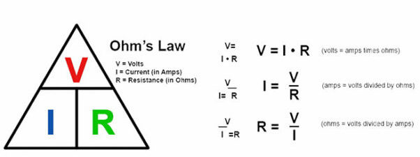
Figure 1 shows the mnemonic many of us have used to learn Ohm's Law. If you can't remember Ohm's Law, the mnemonic lets you quickly find the version of the formula you need. Simply hold your finger over the item you wish to calculate. Cover V (V and E are used interchangeably) and you are left with I * R. Cover R and you see it equals V/I.
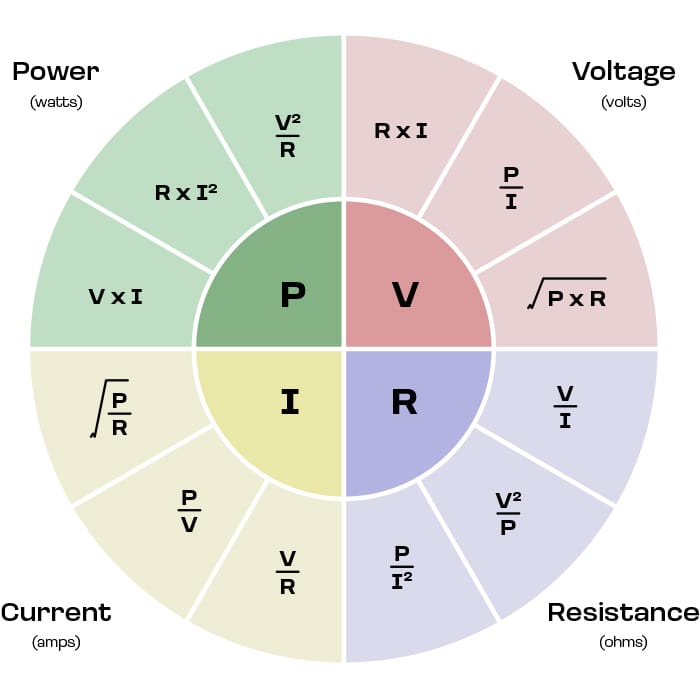
Figure 2 adds in the formulas for power, the most basic of which is P (in watts) = I*V.
Here's a challenge: Look around you right now and find at least one use for Ohm's law.
Here are a two of mine:
Example 1: I've been wondering what it costs to keep my receiver on vs. turning it off when I leave the room. I've been rigorous about turning things off when not in use, but that adds wear and tear to switches and components. Maybe I'd be better off leaving some things turned on? The ammeter in my 13.8 VDC power supply tells me my FTdx10 transceiver draws 2 amps on receive. Two amps times 13.8 VDC = 27.6 watts. The power supply I use is about 60% efficient, so the power supplied from my wall outlet is 27.6 watts divided by 0.6 or 46 watts. During a typical day I might be on the air at any time over about a 10 hour period. If I left the radio on for 10 hours I would use 460 watt-hours (46 watts for 10 hours) or 0.46 kilowatt-hours. I pay my power company, Cobb EMC, 8.25 cents per kilowatt-hour. 0.46 KWh times 8.25 cents equals 3.8 cents. It costs me 3.8 cents to leave my receiver on during a 10-hour day or about a third of a penny per hour. That's not much. It will cost $1.14 a month if I do it every day. Maybe I shouldn't be turning the rig off every time I walk away for a while.
Example 2: Transceivers sometimes work when receiving, then misbehave when attempting to transmit. The misbehavior can manifest itself as indicator lights and/or displays going dim, relays chattering, little or no RF output and/or the radio looping through endless resets. I've seen this many times. It comes up for discussion nearly every day on social media sites dedicated to one transceiver or another. The cause is almost always excessive voltage drop between the power supply and the radio when transmitting. A 100 watt radio draws about 22 amps at 13.8 VDC when transmitting at full power. If the resistance of the wire and connections from the power supply to the radio is just 0.1 ohms, and that's not much, the voltage drop is 22 amps times 0.1 ohms, or 2.2 volts! In this example you may have 13.8 VDC at the power supply, but you will have 11. 6 VDC on the radio. Most manufacturers do not publish a lower threshold for supply voltage, but it's typically around 11 VDC. Below 11 VDC radios do not reliably transmit. On receive there's seldom a problem; the radio only presents a load of one or two amps. On transmit, ohm's law tells us any resistance in the power supply leads above around 0.1 ohms will be problematic.
I'll summarize the March, 2020 Around the Shack column “Station Un-Design Tips,” here, but I encourage everyone to read that column. It can be found in the on-line archives of every newsletter that carries this column and it's Chapter 27 of my book Ham Radio Tips and Tales. In that column I encouraged readers to cast a jaundiced eye on DC power distribution boxes. These are sold as “power hubs,” “power distributors,” “DC outlet panels” or sometimes with vendor-specific names such as West Mountain Radio's “RigRunner” series (clever name). They come in a variety of sizes and from a large number of vendors. They typically use Anderson Powerpole connectors. Figure 3 shows an example.
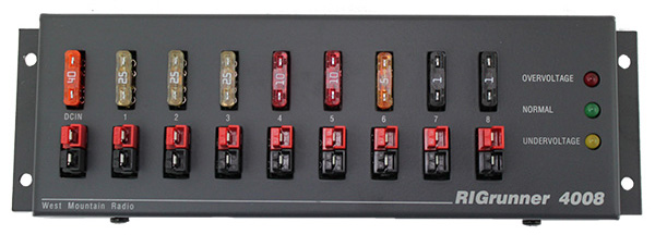
Think through the current flow through one of these distribution boxes. Current enters through a duplex Anderson Powerpole connector. Internally that connector is wired to a fuse holder which has the main fuse plugged in. Further wiring routes the current to a branch-fuse holder with a branch-fuse plugged in. It goes from there to another Anderson Powerpole connector before leaving the box. Is all that less than 0.1 ohms? What do you think?
Not sure? Think about how fuses work. They are made to be resistive, where the power dissipated in the fuse (Ohm's law, P = I2*R) melts it open at the desired trip-point. There are always two fuses in line, the main fuse and the branch-circuit fuse. At 22 amps there is enough voltage drop across just the fuses to make some 100 watt transmitters malfunction. There are additional considerations too, such as your power source might be less than 13.8 VDC, your particular rig may stop working at some voltage above 11 VDC and some allowance needs to be made for the voltage drop across the wire from the power source to the distribution box and the wire from that box to the radio. You can guess my recommendation concerning supplying power to 100 watt transceivers via fused DC power distribution boxes – don't do it!
Back to my challenge - are you stuck for something to calculate using Ohm's law? Here, try this:
End-fed half-wave (EFHW) antennas have become very popular. At the feed point, these have a 49:1 transformer that converts the 50 ohm input to 49*50 = 2,450 ohms, which is the nominal impedance of the radiating wire. For 100 watts at the 50 ohm input, what's the current and what's the voltage? Now, how about 1,500 watts? Now do it again for the 2,450 ohm side of the matching transformer. Are you surprised at the numbers? If you did it correctly, 1,500 watts delivered into 2,450 ohms is 0.78 amps and 1,917 volts, average! The peaks are 1.4 times those numbers or 1.13 amps and 2,700 volts. Look at the insulator feeding the antenna wire on an EFHW transformer box. Does that insulator look okay for 2,700 volts of RF? Under snow? In the rain? Remember also that RF is more prone to arc and cause issues than 60 Hz AC. Can you set the woods on fire this way?
I hope this gets you thinking about applying a modicum of math – just four-function calculator level math – to your everyday ham experiences. The best use of math there is, is Ohm's Law (with due respect to Mr. Cavendish).
73,
Hal N4GG