Introduction: What Is a Go Box?
A "go box" is a self-contained, portable radio station built into a protective case that can be grabbed and deployed at a moment's notice. Whether you're activating a park for POTA (Parks on the Air), setting up a Field Day station, or responding to an emergency communications event, a well-built go box means the difference between being on the air in minutes and spending that same time untangling cables on a picnic table.
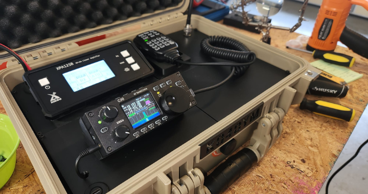
The challenge with any go box is the same: how do you pack a capable, full-featured HF station into something you can actually carry? This article documents my build — a 100-watt HF station based on the Xiegu G90 transceiver and Xiegu XPA125B linear amplifier, housed in an Apache 3800 carry case, with a fully 3D-printed internal structure. Everything you need to reproduce this build is here: parts lists, links, 3D files, wiring details, and lessons learned the hard way.
Design Goals
Before buying a single component, it helps to define what you actually want out of the station. My goals were:
- Portable and self-contained. Everything needed to get on the air — except power and an antenna — lives in the box.
- 100 watts. Enough power to make reliable contacts under less-than-ideal conditions, which ruled out QRP-only builds.
- Digital mode capable. FT8 and other weak-signal digital modes are essential for EMCOMM and POTA alike.
- Rugged. The box needs to survive being tossed in the back of a vehicle.
- Clean and reproducible. No rats' nest of cables taped to the walls. If a fellow ham wants to build the same thing, they should be able to.
Bill of Materials
Core Components
| Item | Notes |
|---|---|
| Xiegu G90 HF Transceiver | 20W SDR transceiver with built-in ATU and detachable display |
| Xiegu XPA125B Power Amplifier | 100–125W solid-state linear amp with built-in ATU and 2.7" LCD |
| Xiegu DE-19 Expansion Adapter | USB interface for digital modes; links G90 to XPA125B automatically |
| Apache 3800 Carry Case | High-impact PP case, IP65 rated, ~16.5" × 13" × 6.8" exterior |
| Xiegu MH-01 Hand Microphone | Comes bundled with the G90 |
Cables and Adapters
| Item | Purpose |
|---|---|
| RF Coaxial UHF Female SO-239 to MCX Male Right Angle Adapter | Short RF jumpers between G90, XPA125B, and lid SO-239 port |
| DB-9 Serial Extension Cable | G90 remote display head extension to lid panel |
| 40 Pin FFC Ribbon Cable, A Type, 300mm | XPA125B display extension — first cable segment |
| 40 Pin FFC Ribbon Cable, B Type, 250mm | XPA125B display extension — second cable segment |
| 40 Pin FPC Extension Union | Joins the two ribbon cable segments together |
| USB-C Panel-Mount Extension Cable | DE-19 USB-C to lid-mounted USB-C connector |
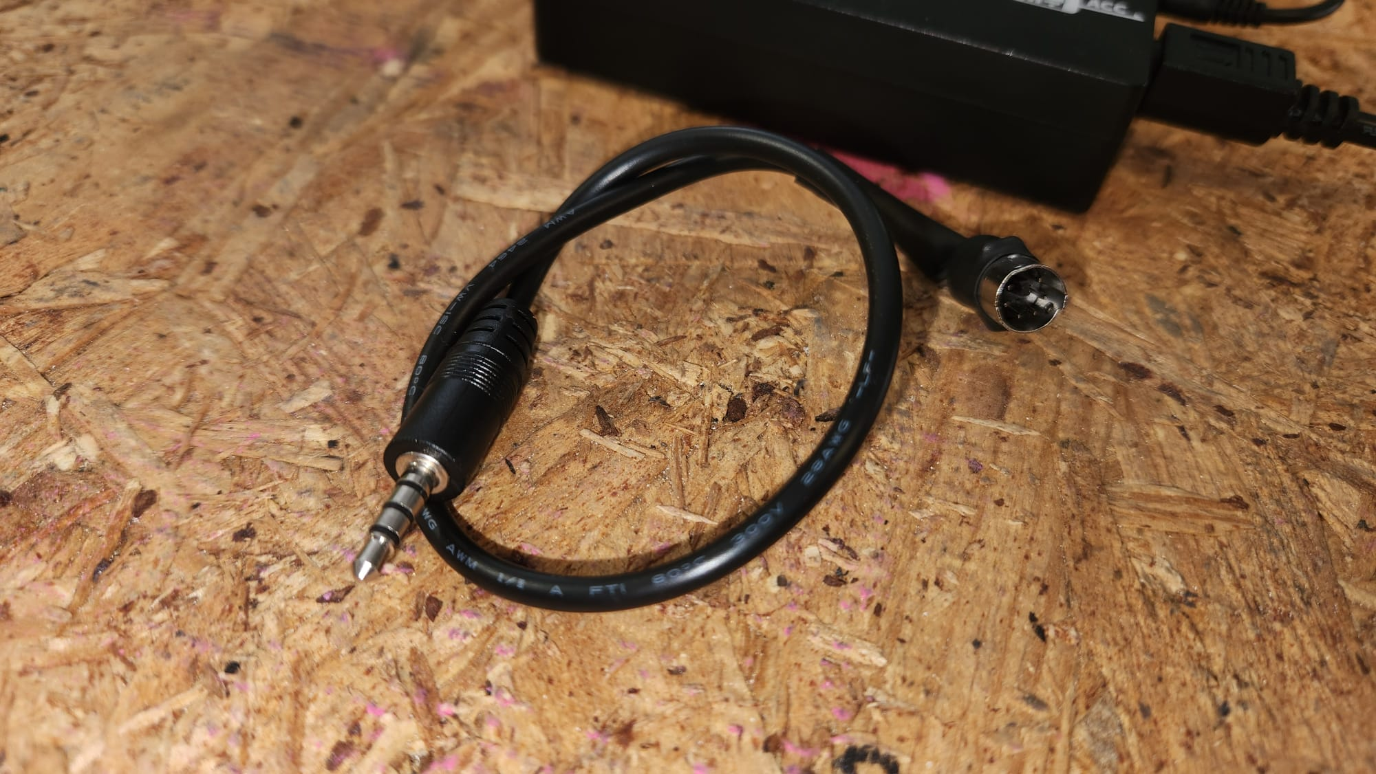
| 6-pin DIN Connector (modified) | XPA125B accessory/interface port — shell trimmed to fit space |
| Anderson Powerpole Panel-Mount Connector | Power inlet on lid |
| SO-239 Panel-Mount Connector | Antenna port on lid |
3D Printed Parts
All files are free on Thingiverse: https://www.thingiverse.com/thing:7313848
| File | Purpose |
|---|---|
| HamRadioGoBox-Base-Top-Left.stl | Internal chassis (base), top-left section |
| HamRadioGoBox-Base-Bottom-Left.stl | Internal chassis (base), bottom-left section |
| HamRadioGoBox-Base-Top-Right.stl | Internal chassis (base), top-right section |
| HamRadioGoBox-Base-Bottom-Right.stl | Internal chassis (base), bottom-right section |
| HamRadioGoBox-Lid-Top-Left.stl | Lid panel, top-left section |
| HamRadioGoBox-Lid-Top-Right.stl | Lid panel, top-right section — includes MH-01 mic cradle |
| HamRadioGoBox-Lid-Bottom-Left.stl | Lid panel, bottom-left section |
| HamRadioGoBox-Lid-Bottom-Right.stl | Lid panel, bottom-right section |
| HamRadioGoBox-Antenna-Socket.stl | Antenna socket bracket/mount for the lid |
| PowerPole_Simple_Notch.STL | Anderson Powerpole panel mount — by Electroalex26 |
| PowerPole_Nut.STL | Anderson Powerpole panel nut — by Electroalex26 |
Consumables / Misc
- PLA filament (any brand) — see note on material choice in the Lessons Learned section
- M3 hardware (screws/nuts as needed for panel connectors)
- Short lengths of coax
The Components
Xiegu G90 — The Brains
The G90 is a 20-watt SDR-based HF transceiver covering 0.5–30 MHz receive and all amateur bands from 160m through 10m for transmit. It supports SSB, CW, and AM, includes a built-in automatic antenna tuner, and features a real-time spectrum scope and waterfall on a 1.8-inch colour display. What makes it ideal for a go box is its detachable front panel: the display head connects to the main body via a standard DB-9 cable, which means you can mount the radio body inside the case and route the display wherever you want.
Operating voltage is 12–15V DC with a maximum TX current draw of around 8A. At full power the radio is compact — about 2 × 5.5 × 9.8 inches — and weighs 3.6 lbs.
Xiegu XPA125B — The Power
The XPA125B takes the G90's 20W and turns it into up to 125W. It's a solid-state linear amplifier covering 0.5–54 MHz, with a built-in automatic antenna tuner, a 2.7-inch LCD showing output power, SWR, voltage, current, and temperature, and automatic band tracking when paired with the G90 via the DE-19. At 13 dB of gain, you can back the G90 down to just a few watts and let the amp do the work.
The XPA125B draws up to 30A at 13.8V under full output. It originally ships in its own metal enclosure measuring about 10.3 × 6.3 × 2.8 inches. As we'll see, that enclosure had to go.
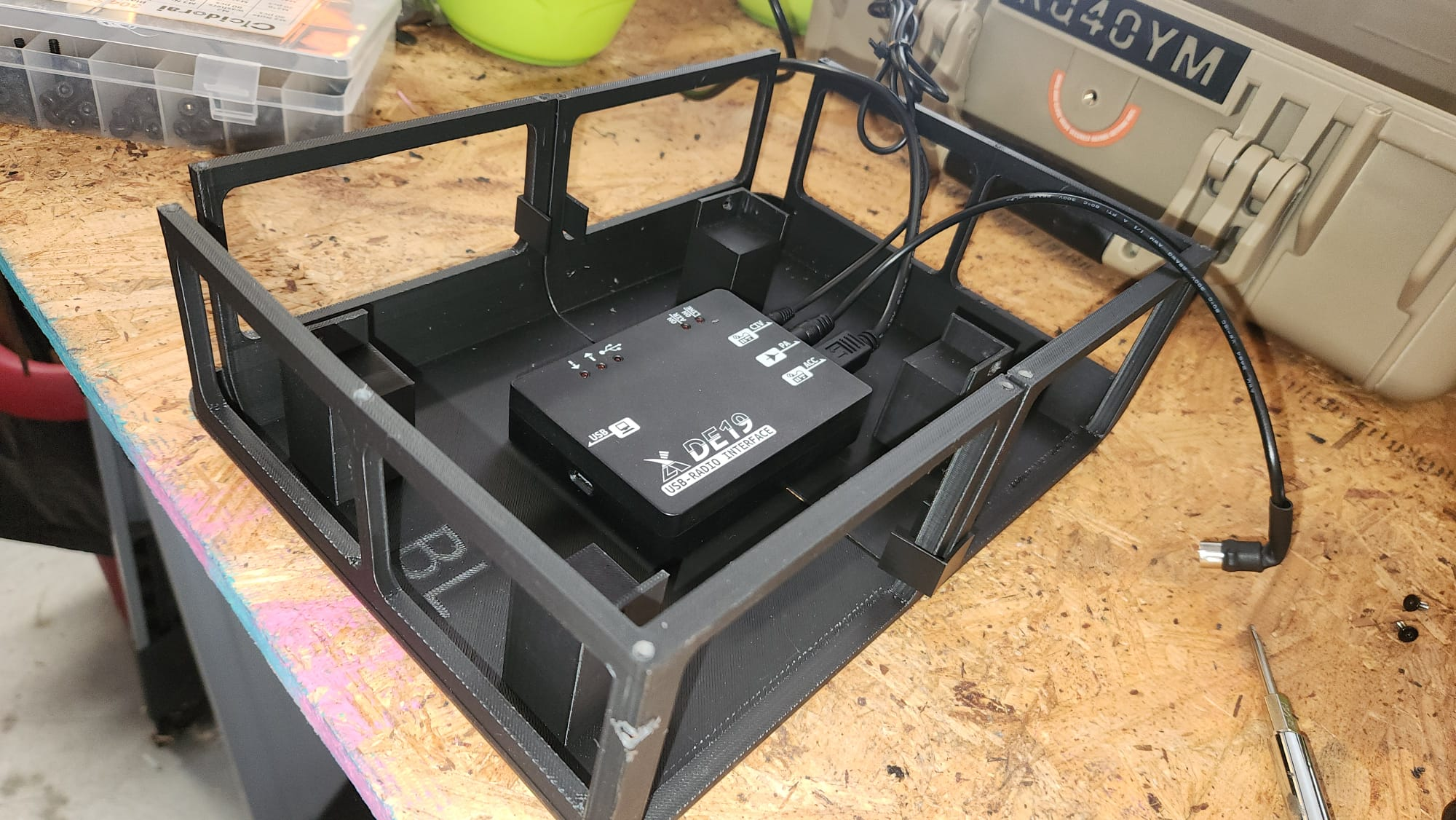
Xiegu DE-19 — The Bridge
The DE-19 is a small expansion adapter that sits between the G90 and a connected PC. It provides isolated audio in/out for digital modes (FT8, JS8Call, etc.), plus a CIV (CAT control) interface. Crucially for this build, it also has a dedicated XPA125B port that passes PTT, ALC, and band data to the amplifier, enabling fully automatic band-switching and power control when you change bands on the G90. The DE-19 connects to the radio via its ACC Mini-DIN6 port and to the XPA125B via the amplifier's accessory port.
Apache 3800 — The Enclosure
The Apache 3800 is a well-regarded protective carry case in the ham radio community. The exterior measures approximately 16.5" × 13" × 6.8", with a usable interior of about 14-7/8" × 10-5/8". It's rated IP65 (dustproof and water-resistant), has a built-in pressure relief valve for air travel, a latching lid with a built-in stay that props it open during operation, and comes with a pick-and-pull foam insert — which we'll be removing entirely in favour of the 3D-printed structure.
The Challenge: It Doesn't Fit
Here's the honest truth about this build: the XPA125B does not fit in the Apache 3800 in its original enclosure. The amp's own case adds too much to its overall depth. The interior of the 3800 simply cannot accommodate the amp with its case intact.
The solution is to remove the XPA125B from its original metal enclosure entirely. This frees up the depth you need, but creates the next problem: the rear-panel connectors on the XPA125B — the RF antenna jack, the 6-pin DIN accessory port, the ACC connectors — all protrude far enough that they'd either hit the wall of the Apache case or leave no room for proper cables to connect.
This is where the build gets creative.
Dismantling the XPA125B
⚠️ Note: Removing the XPA125B from its case voids any warranty and involves working with RF amplifier circuitry. Proceed carefully. Disconnect all power before disassembly.
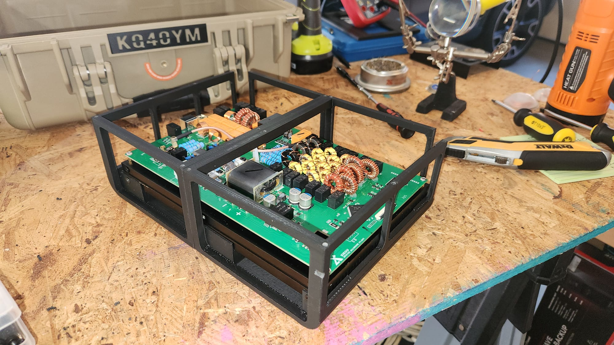
The XPA125B's internal structure is built around a large aluminium heatsink, which acts as both the thermal mass for the power transistors and the structural backbone of the whole assembly — the PCB is mounted directly onto this heatsink, and the case panels are in turn attached to it. To disassemble, remove all the screws from the enclosure panels and carefully separate them from the heatsink. You'll be left with the heatsink and PCB assembly, with the front display panel attached and all rear connectors exposed.
The 3D-printed internal chassis is designed to cradle this heatsink assembly directly, holding it securely in position inside the Apache case.
Solving the Connector Problem
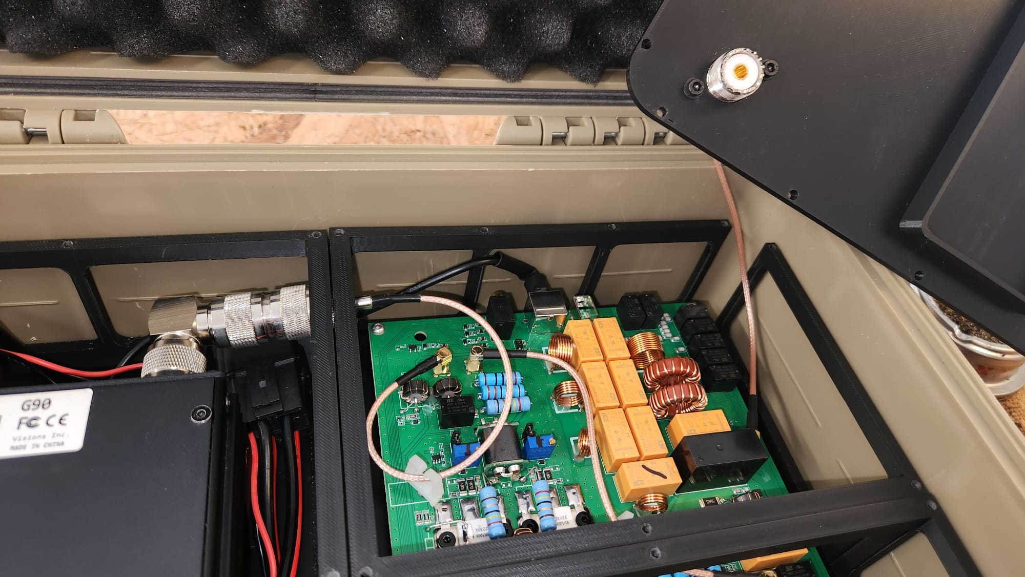
With the XPA125B stripped of its case, the rear connectors now sit very close to the walls of the Apache 3800. There is not enough clearance for standard coax connectors or cables. Two custom solutions were needed.
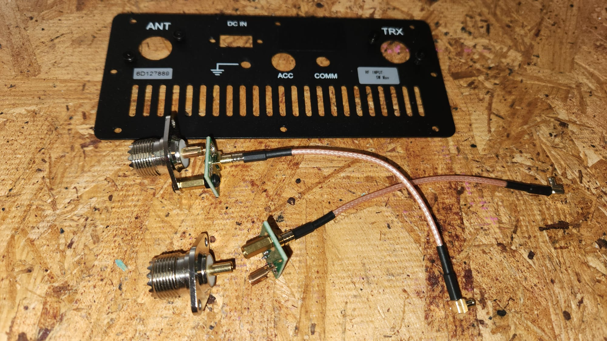
RF Connectors: SO-239 to MCX Right-Angle Adapters
The antenna connections between the G90, the XPA125B, and the lid-mounted SO-239 panel jack are made using UHF Female (SO-239) to MCX Male Right-Angle adapter cables. These short, low-profile jumpers solve two problems at once: they provide the 90° turn needed to route the coax along the case wall rather than straight out the back, and they keep the connection length as short as possible, minimizing any RF loss.
You'll need two of these adapters:
- One to connect the G90's antenna output to the XPA125B's input
- One to connect the XPA125B's antenna output to the SO-239 port mounted in the lid
6-Pin DIN: Trimming the Shell
The XPA125B accessory/interface port uses a 6-pin DIN connector. A standard 6-pin DIN plug is bulky enough that it won't fit in the gap between the XPA125B board and the Apache case wall once everything is assembled.
The fix is simple but requires a bit of metalwork: take a standard 6-pin DIN plug and trim down the outer metal shell with a rotary tool or file until the overall diameter of the connector is small enough to fit in the available space. The pins and internal contacts are left untouched — only the protective outer shell is shortened. The result is a functional connector that fits where a stock one wouldn't.
3D Printed Structure: The Internal Chassis
The heart of this build is an entirely 3D-printed internal structure that replaces the Apache 3800's foam insert. The files are all available for free at https://www.thingiverse.com/thing:7313848.
Print Settings
These parts were printed in PLA with the following settings:
- Layer height: 0.2 mm
- Infill: 15%
- Supports: Required — enable support structures in your slicer
- Material: PLA (standard, no special requirements)
Both the G90 and the XPA125B heatsink assembly are substantial in weight, so don't be fooled by the low infill figure. The 2mm walls in the printed parts carry the load well enough for a first version, and the parts performed fine in practice — but if you want a more robust build, increasing infill to 25–30% is a straightforward improvement.
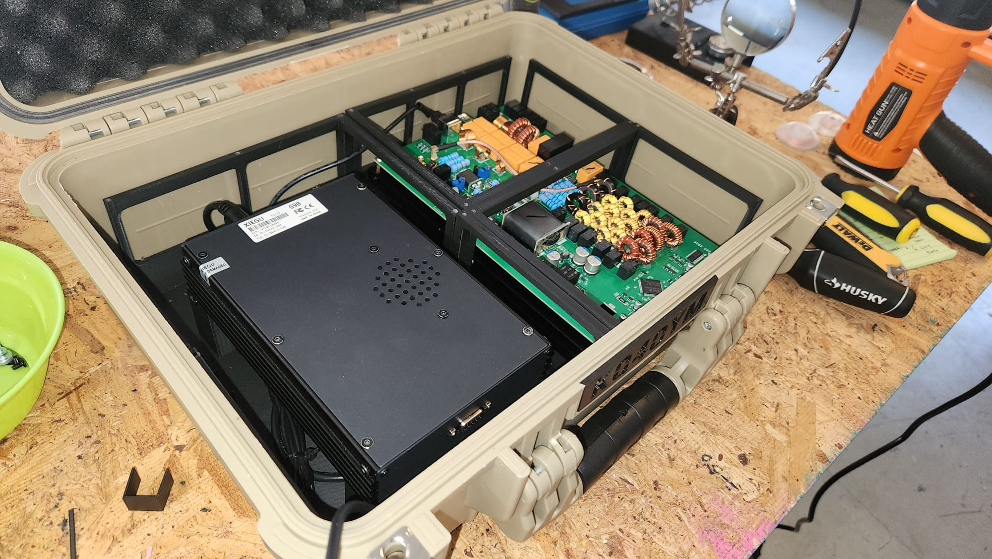
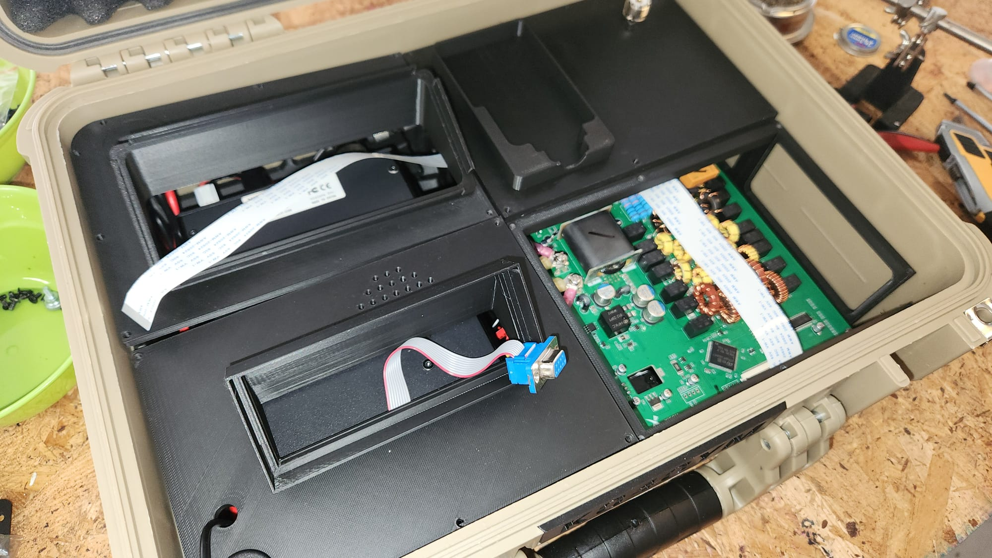
Internal Structure (4 Parts)
The internal chassis consists of four interlocking parts (Base-Top-Left, Base-Bottom-Left, Base-Top-Right, Base-Bottom-Right) that together form a cradle securing both the G90 (with its main board) and the bare XPA125B board in their correct positions inside the case. The parts are designed to hold everything snugly without screws, relying on friction-fit and the geometry of the components themselves.
Print all four parts and test-fit them in the case before installing any electronics. They should sit flat on the base of the Apache 3800 and leave enough room at the rear for the connector solutions described above.
Installing the DE-19
The DE-19 expansion adapter is installed directly below the G90 in its cradle. It's not screwed or velcroed into place — instead, the cables that connect it to the G90's ACC port and to the XPA125B's accessory port are short enough that the DE-19 is held firmly in position by cable tension alone. This keeps the installation clean and makes it easy to service if needed.
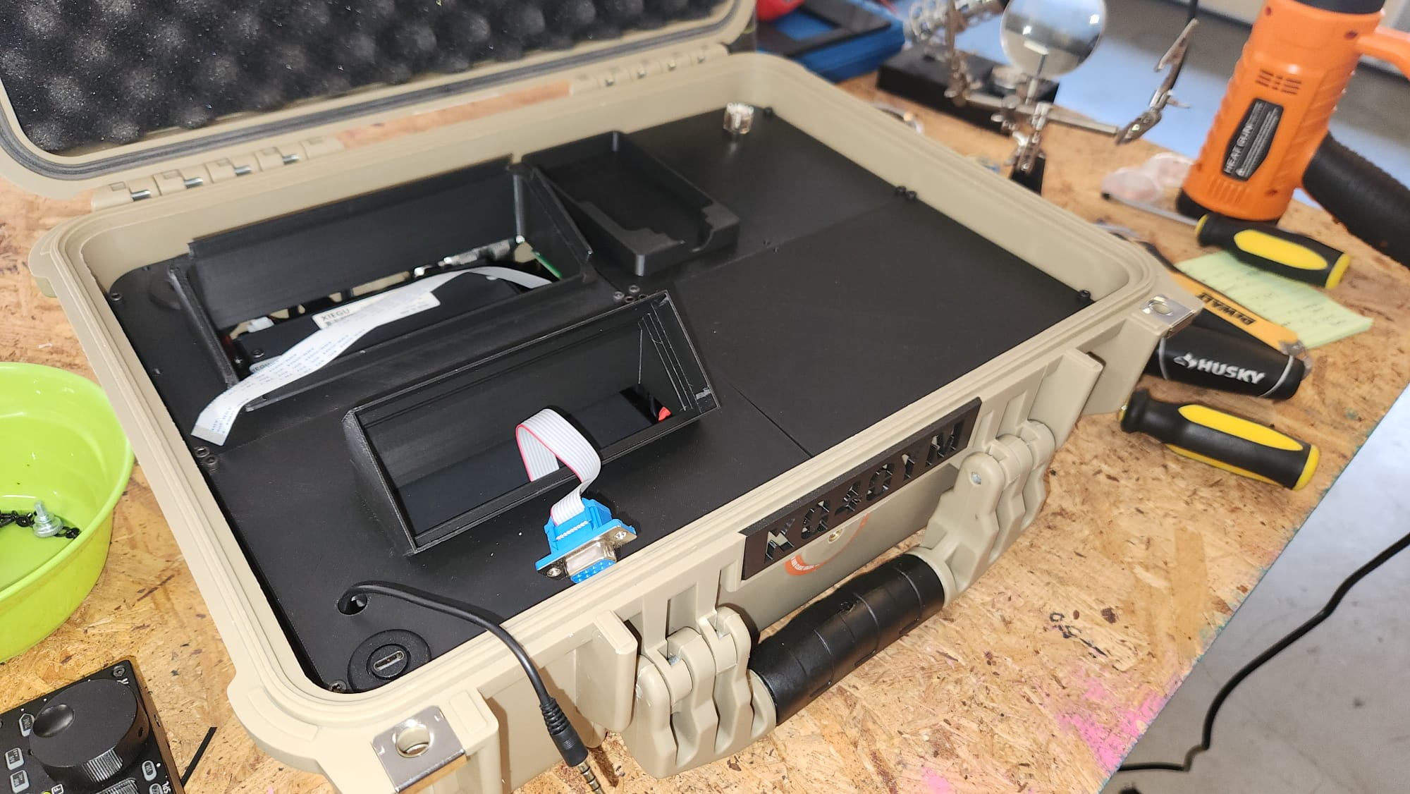
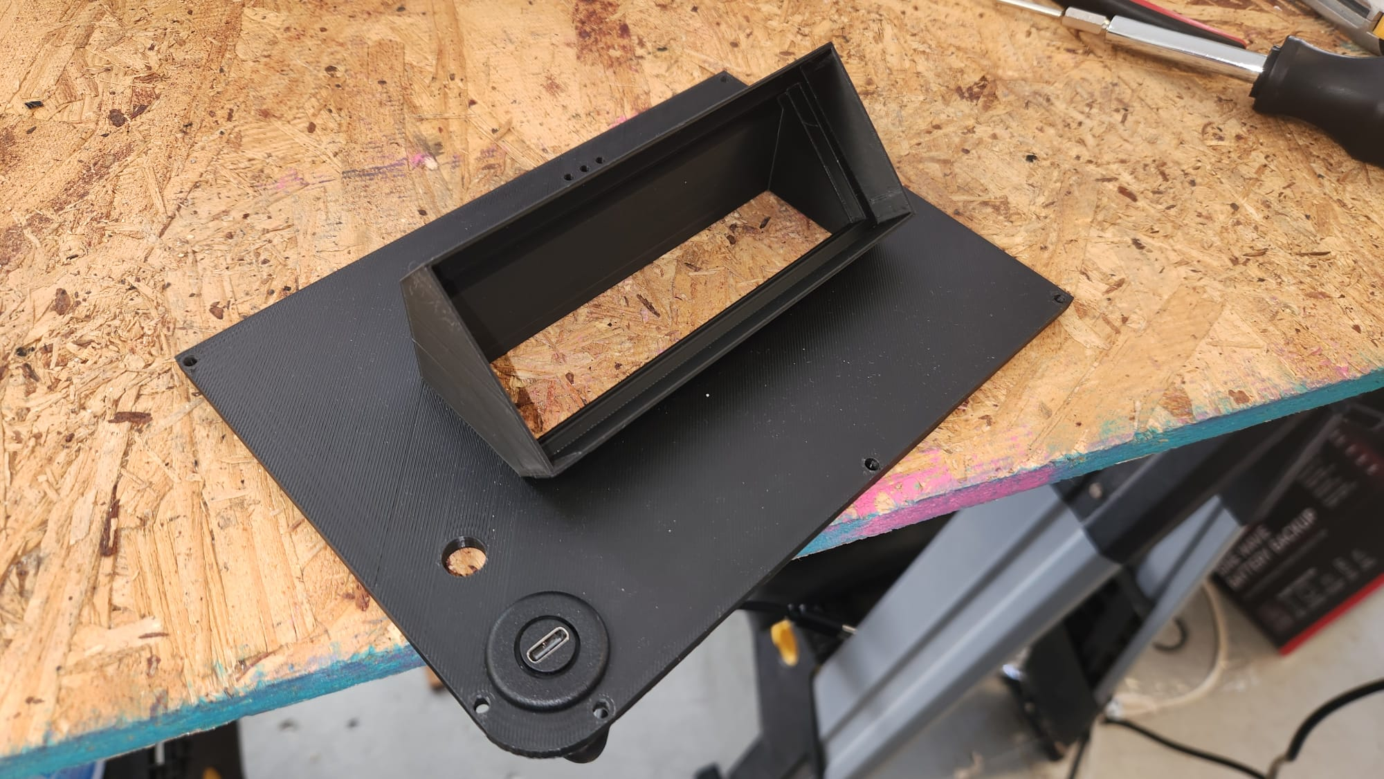
The Lid Panel
The lid of the Apache 3800 gets its own four-part 3D-printed panel that transforms it into the operator interface for the station. When the lid is propped open (the Apache 3800 has a built-in stay that holds the lid at a fixed angle), you have clear visibility and access to everything you need to operate.
The lid panel houses:
- G90 display head — the remote front panel of the transceiver
- XPA125B 2.7" LCD display — for monitoring power output, SWR, and amplifier status
- SO-239 antenna port — via the printed HamRadioGoBox-Antenna-Socket.stl bracket
- Anderson Powerpole power inlet — using the PowerPole_Simple_Notch.STL and PowerPole_Nut.STL parts (by Electroalex26, Thingiverse)
- USB-C panel connector — for connecting a laptop for digital mode operation (routed to the DE-19 inside)
- MH-01 microphone cradle — a built-in holder for the Xiegu MH-01 hand mic, integrated into the top-right lid panel section (HamRadioGoBox-Lid-Top-Right.stl)
Printing the Lid Parts
Print all five lid-related parts — the four panel sections (Lid-Top-Left, Lid-Top-Right, Lid-Bottom-Left, Lid-Bottom-Right) plus the HamRadioGoBox-Antenna-Socket.stl — using the same settings as the internal chassis (PLA, 0.2mm, 15% infill, supports on). Also print the two PowerPole parts (PowerPole_Simple_Notch.STL and PowerPole_Nut.STL). The lid parts mount to the inside face of the Apache 3800 lid. Before gluing or fastening anything, do a full dry-fit to confirm the display cutouts align with your display positions and all connector holes are where you expect them.
Relocating the Displays
Both the G90's detachable head and the XPA125B's LCD panel need to be extended from their normal positions on the front of each unit to the lid panel. This requires two different extension solutions.
G90 Display: DB-9 Extension Cable
The G90's display head connects to the main unit via a standard DB-9 (9-pin serial) cable. This is the same cable included with the radio for remote head use. To route the display to the lid, simply use a standard DB-9 serial extension cable. Route the cable neatly inside the case from the G90 body to the display position in the lid panel. The G90 is designed for remote head operation, so this works perfectly without any modification.
XPA125B Display: 40-Pin Flat Ribbon Cable Extension
The XPA125B's display uses a 40-pin FPC/FFC flat ribbon cable (0.5mm pitch) internally. To relocate it to the lid, you need to extend this ribbon cable using two cable segments and a union connector. The three parts you need are:
- 40 Pin FFC Ribbon Cable, A Type, 300mm
- 40 Pin FFC Ribbon Cable, B Type, 250mm
- 40 Pin 0.5mm FPC Extension Connector Adapter (union)
One A Type and one B Type cable are needed because the connector on the XPA125B PCB and the display module face in opposite orientations — using one of each type, joined with the extension connector adapter, correctly routes all 40 pins without any signal inversion. The combined length of the two cables (300mm + 250mm = 550mm) gives you enough slack to route the cable neatly to the lid panel.
Take care when handling the ribbon connectors — they're fragile and the ZIF (zero insertion force) locking tabs on the PCB can break if forced. Lift the locking tab gently before inserting or removing the cable, and keep the bends gentle — a tight kink in an FPC cable can damage or sever the conductors.
External Connectors on the Lid
Three external connections are brought out to the lid panel for a clean, permanent interface to the outside world.
Power: Anderson Powerpole
Anderson Powerpole connectors are the de facto standard for 12V DC in amateur radio. The lid carries a panel-mounted Powerpole connector that feeds power into the box. From there, power is distributed internally to the G90 and XPA125B. Make sure your wiring is heavy enough to handle the XPA125B's peak draw of up to 30A — use at least 12 AWG wire between the Powerpole connector and the amplifier, and 16 AWG is sufficient for the G90.
Antenna: SO-239
A standard panel-mount SO-239 (UHF Female) jack is installed in the lid. Your antenna connects here via a standard PL-259 plug. Inside the box, a short SO-239-to-MCX right-angle adapter jumper routes the RF to the XPA125B output connector as described earlier.
Digital Modes: USB-C Panel Connector
A USB-C panel-mount connector in the lid carries the laptop connection to the DE-19 inside. When you want to run digital modes, plug a USB-C cable from your laptop into this connector and you're connected to the DE-19's USB port for audio and CAT control.
Assembly Sequence
If you're building this yourself, this is the order that makes the most sense:
- Print all 11 parts: 4 internal chassis (Base-), 4 lid panel sections (Lid-), the Antenna-Socket, and the two PowerPole parts. Remove all supports and test-fit everything before going further.
- Dismantle the XPA125B from its enclosure. Set the enclosure aside.
- Trim the 6-pin DIN connector shell and verify it will fit in the available space.
- Dry-fit the internal chassis in the empty Apache 3800. Place the bare XPA125B and G90 in their positions to confirm fit and connector clearance.
- Install panel connectors in the lid panel pieces: SO-239 antenna jack, Anderson Powerpole, USB-C panel mount.
- Mount the lid panel pieces inside the Apache 3800 lid.
- Install the G90 and XPA125B in the internal chassis.
- Install the DE-19 below the G90 and connect it to the G90 ACC port and XPA125B accessory port.
- Route and connect the display cables: DB-9 for the G90 head; 40-pin ribbon extension for the XPA125B display. Mount both displays in the lid panel.
- Install the SO-239→MCX RF jumpers between G90 output, XPA125B input, and the lid antenna port.
- Connect the trimmed 6-pin DIN to the XPA125B interface port.
- Route the USB-C extension from the DE-19 to the lid USB-C panel connector.
- Connect the power wiring from the lid Powerpole connector to the G90 and XPA125B power inputs.
- Dress and secure all cables inside the case.
- Close the lid gently and verify nothing is being pinched by the display cables or other wiring.
First Power-On and Testing
Before connecting an antenna or transmitting, do a bench test with a dummy load:
- Connect a 12V supply to the Powerpole connector. Both the G90 and XPA125B should power on. Verify both displays light up in the lid.
- Check that the G90 display is fully responsive — all buttons, the VFO knob, and menu navigation should work normally.
- Verify the XPA125B display shows the correct idle readings.
- Connect the DE-19 to a laptop and confirm the G90 is visible as a CAT-controllable radio and that audio in/out works.
- Connect a dummy load to the antenna port on the lid.
- Transmit a short carrier on each band and verify the XPA125B follows band changes automatically (this confirms the DE-19's band data link is working).
- Check output power and SWR on the XPA125B display.
If the amp isn't following band changes automatically, check the DE-19 XPA125B port connection and make sure the band data cable is fully seated.
Lessons Learned
Measure three times before printing. The internal structure was designed around the specific dimensions of the bare XPA125B board, not the boxed unit. If you have a different revision of the XPA125B, the board dimensions may differ slightly. Always dry-fit before assuming the prints are correct.
Ribbon cables are fragile. The 40-pin FPC cable on the XPA125B display is the most delicate part of the whole build. Be gentle with the ZIF connector tabs and don't route the cable sharply. Give it a gentle curve rather than a tight bend.
Short coax jumpers matter. The SO-239-to-MCX adapters solve both a mechanical problem and an RF problem. The shorter the path between the G90, amp, and antenna port, the less loss and the fewer potential points of failure.
The 6-pin DIN modification takes patience. A rotary tool (Dremel) with a cutting disc makes the job easier than a file. Work slowly and check the fit frequently — you want to remove just enough material.
PLA is a workable but not ideal material for this build. PLA starts to soften around 60°C, which is a real concern in an enclosed case with no ventilation — and the XPA125B at full output generates significant heat. This first version uses PLA and has held up fine for initial testing, but PETG is a better choice: it's only slightly harder to print and has a heat deflection temperature nearly double that of PLA. If you're building your own version, print in PETG from the start. A future revision of this build may add ventilation to the case, which would also help.
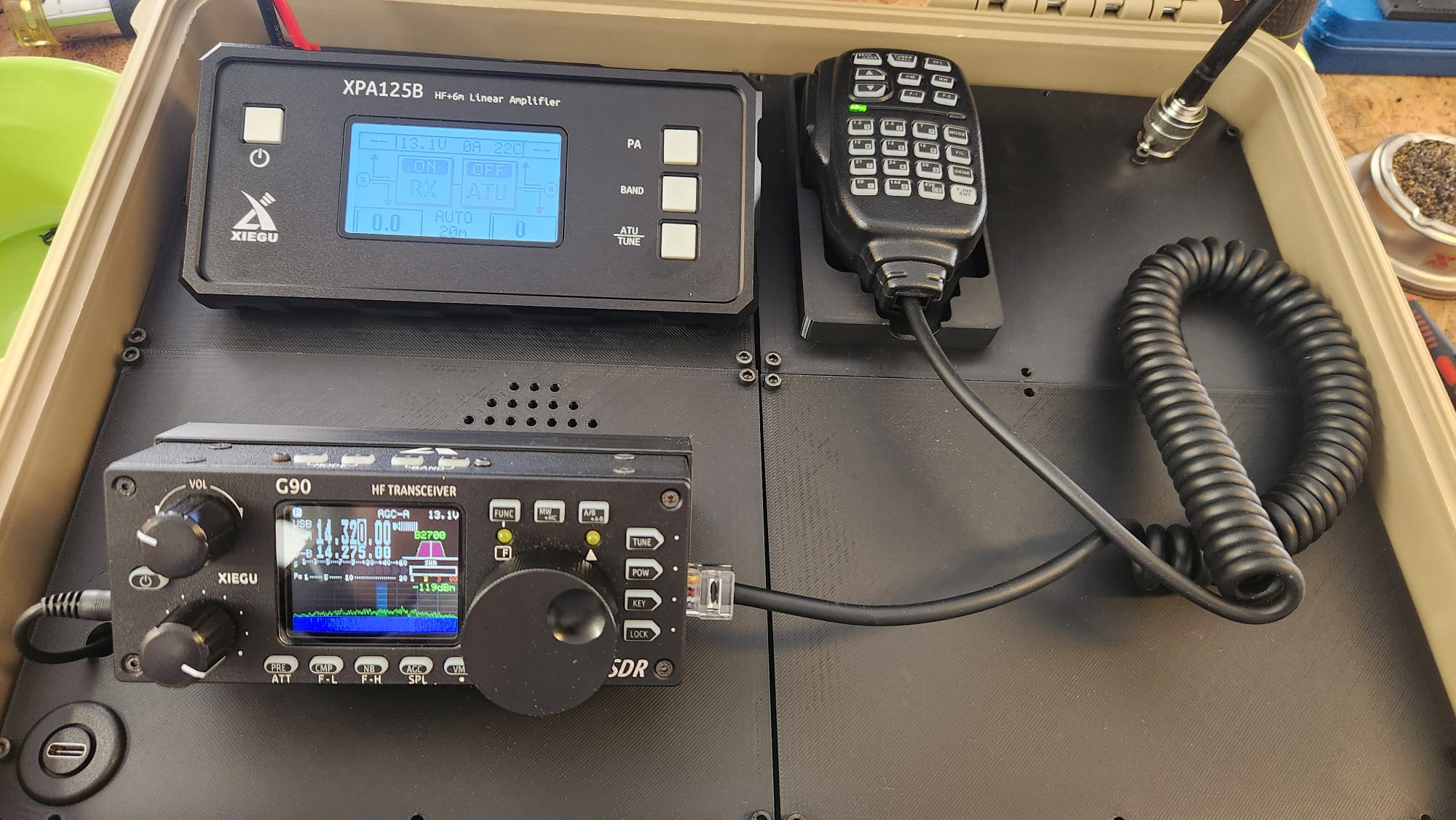
Operating the Station
In the field, operation is straightforward. Open the Apache 3800 — the lid stays propped open by the built-in lid stay — and you're looking at both displays and all your controls. Connect your 12V supply (a LiFePO4 battery is ideal for POTA and Field Day), connect your antenna to the SO-239 lid port, and power on.
For digital modes, connect a USB-C cable from your laptop to the lid's USB-C port. The DE-19 handles all audio routing and CAT control. The XPA125B will track band changes from the G90 automatically via the DE-19's band data output.
The MH-01 microphone sits in its printed cradle in the top-right of the lid panel, ready to grab. No digging around in a bag.
Get the Files
All 3D files for this build are freely available on Thingiverse:
https://www.thingiverse.com/thing:7313848
The Thingiverse page includes all 11 STL files: 4 internal chassis (Base) parts, 4 lid panel parts (including the mic cradle in HamRadioGoBox-Lid-Top-Right.stl), the HamRadioGoBox-Antenna-Socket.stl bracket, and two Anderson Powerpole panel-mount parts (PowerPole_Simple_Notch.STL and PowerPole_Nut.STL, originally designed by Electroalex26 and included with permission).
Final Thoughts
This build took some problem-solving — the XPA125B case removal, the connector clearance issues, and the ribbon cable extension for the amp display were all challenges that required specific solutions. But the result is a station that deploys in minutes, runs 100 watts on any HF band, handles digital modes natively, and fits in a case you can carry in one hand.
If you build your own version, I'd love to hear about it.
73 de KQ4OYM.
Quick Reference: Key Links
- 3D Files: https://www.thingiverse.com/thing:7313848
- Xiegu G90: https://xiegu.eu/product/xiegu-g90-hf-20w-sdr-transceiver/
- Xiegu XPA125B: https://xiegu.eu/product/xpa125-100w-solid-state-linear-amplifier/
- Xiegu DE-19: https://xiegu.eu/product/xiegu-de-19-usb-expansion-adapter/
- 40-pin FFC ribbon cable, A Type 300mm: https://a.co/d/00OQHeOM
- 40-pin FFC ribbon cable, B Type 250mm: https://a.co/d/0ji9KiNv
- 40-pin FPC extension connector (union): https://a.co/d/0i3Z6GnJ
- PowerPole panel mount (Electroalex26): https://www.thingiverse.com/thing:3726066