The Tale of the Wire Kabob - A Dubious Invention Or In Defense of Analysis
My new end-fed half-wave (EFHW) antenna consists of a 132-foot radiating wire fed via a 49:1 matching transformer. The transformer brings the impedance of the wire to 50 ohms, more or less. It's definitely “more or less.” EFHWs are high impedance antennas and their characteristics are sensitive to their surroundings. My store-bought EFHW came with a small in-line coil six feet out from the matching transformer. That coil is there to add a small amount of inductance to lower the antenna's resonant frequency on 10 meters. This is a tried and true approach to getting an EFHW antenna to cover all the ham bands from 80 through 10 meters, again, “more or less.”
Unfortunately, but predictably, the resonant frequency of my EFHW was too high in the 10-meter band for my preferred operating modes. The addition of more inductance into the radiating wire, six feet from the matching transformer, was in order. Meanwhile, the 132-foot radiating wire with its existing in-line coil was well-made from one continuous piece of wire. Adding inductance meant splicing into the wire – something I preferred not to do. I wanted a way to wrap some of the existing wire onto a coil-form without making a splice.
Well, I invented something, or, at least, I devised something. I have a strong suspicion the item I came up with has been devised before, probably by lots of people. Or maybe not. I've decided not to look.

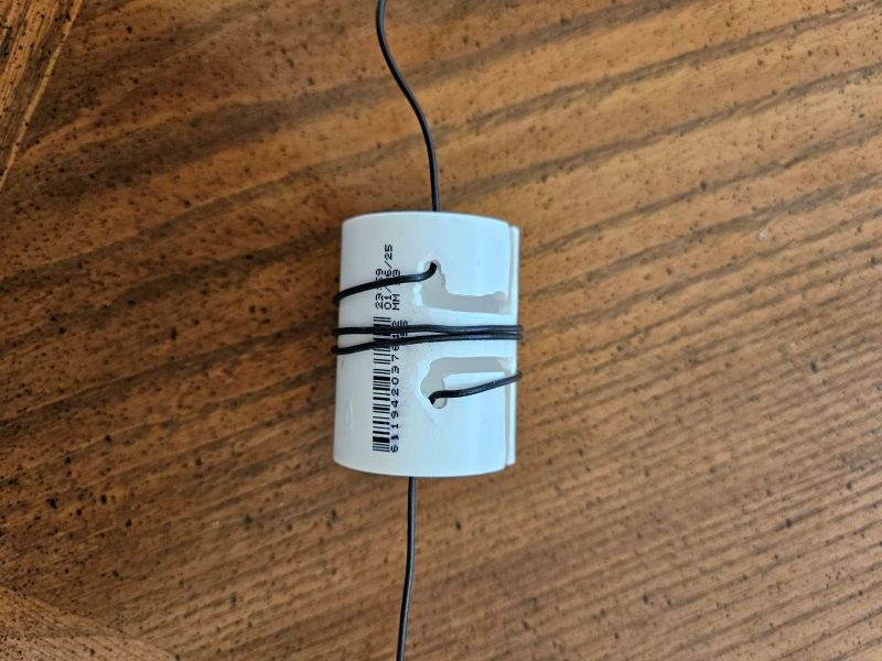
Figure 1. The “Wire Kabob” for splice-free addition of a coil onto an existing wire.
Figure 1 shows my “invention.” It's a short length of PVC pipe notched to allow taking some of an existing wire and forming it into a coil, without cutting the wire. The design resulted from sketch-pad noodling and some crude hand-work with a drill.

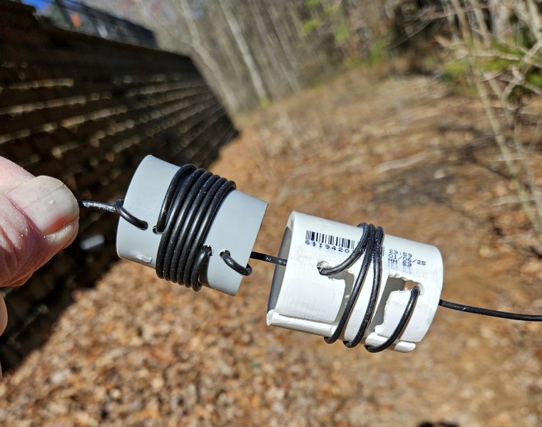
Figure 2. Table-top mechanical test of the first wire kabob. There may never be a second one.
Figure 2 shows a table-top test of the device using a length of #14 THHN house wire.

Figure 3. The new coil added to my EFHW antenna. It had no effect on resonant frequency.
Figure 3 shows the new coil in place, in series with the preexisting coil, installed without cutting the wire. Success! I have named this little gizmo a “wire kabob.” If you have a better name, please email me.
Results from installing the wire kabob were, to say the least, disappointing. In fact, there were no measurable results at all. The wire kabob was a mechanical success that had no effect electrically. Adding inductance should have lowered the antenna's resonant frequency and it didn't.
Last month I encouraged readers to use Ohm's Law as often as they can. Ohm's Law only requires a four-function calculator to handle the math. Why not analyze what you want to do before you do it? Why not “run the numbers” before incurring the time and expense of trial and error? (I acknowledge trial and error is sometimes fun and educational). Did I take my advice this time, as I expended the effort to design, build and experiment with the wire kabob? No, I just charged ahead.
Not lost on me was the fact that as I wrapped wire onto the wire kabob I was shortening the antenna. But I didn't bother analyzing it and here's why. Straight wire is slightly inductive but not nearly as much as wire formed into a coil. Intrinsically it seemed losing inches of straight wire in favor of having those inches form a coil had to lower the antenna’s resonant frequency. It didn't work that way. Adding more and more wire onto the wire kabob had no effect on the resonant frequency. How could that be?
Here's the simple answer. As you add inductance at or near the base of an antenna, a wire vertical for example, the resonant frequency goes down. But, also, as you shorten the length of an antenna the resonant frequency goes up. If you make an in-line loading coil using the existing wire, you are lowering and raising the resonant frequency at the same time. The two actions tend to cancel. It seems obvious now that I've written it down.
I wound up analyzing my specific case. The two actions - adding the coil and shortening the antenna – almost perfectly canceled. That agrees with what I observed. Adding more turns to the coil accomplished nothing. It's important to note however that the results are case-specific. For example, if you were to make the new coil very long yet with very few turns, it would add little inductance and use a lot of wire. That would raise the resonant frequency. Conversely, a small tightly wound coil would add a lot of inductance and not use much wire, lowering the resonant frequency. The good news is this can be successfully modeled if you are inclined to analyze it before you try it.
Table 1 shows three cases for adding inductance into my EFHW. The second column shows the amount of change in the resonant frequency I would have expected if I ignored the fact that the wire for the coil shortens the antenna. Per column two, adding 1 uH of inductance would have lowered the resonant frequency 45 KHz – just what I was looking for and didn't see. The third column is the result of an EZNEC analysis taking into consideration the shortening of the antenna. The analysis predicts the effect will be so small as to be unobservable and that's how it turned out.
|
Added Inductance |
Expected Change |
Calculated Change |
Observed Change |
|
0.5 |
-19 |
+10 |
None |
|
0.75 |
-34 |
+1 |
None |
|
1.0 |
-45 |
-3 |
None |
Table 1. Calculated vs. Observed Change from Adding a Coil
Table 2 shows the amount of wire used to make the experimental coils. I'm still surprised a 1 uH coil made with the dimensions I was using (coil diameter 1.5 inches, coil length 1 inch, 5.4 turns) used over two feet of wire. The formula is just the circumference of the coil times the number of turns.
|
Added Inductance |
Amount of Wire Used |
|
0.5 |
17.9 |
|
0.75 |
21.9 |
| 1.0 |
25.5 |
Table 2. Coil Wire Length
There are a few lessons here. First, analysis can sometimes save a lot of time and/or expense.
Next, it’s easy to fool yourself. Despite sixty-four years in ham radio my assumptions about adding inductance while ignoring wire shortening, and, about how much wire I was using, and, about the sensitivity of an EFHW to changes in its length were all wrong. Analysis has its place.
As to the future of the wire kabob – well, I don’t know. It’s a dubious invention at best. Mine is resting in the trash can in the garage.
73,
Hal N4GG

Great article Hal, I have been playing with EFHW's for the last 5 years, and I like them a lot.
Lee N4WYE